You finally have your salt spray chamber, and you're ready to start testing products for corrosion resistance before they go to market. This guide will walk you through everything you need — from unpacking and installation to startup and daily operation.
Installing & Setting Up a Salt Spray Chamber
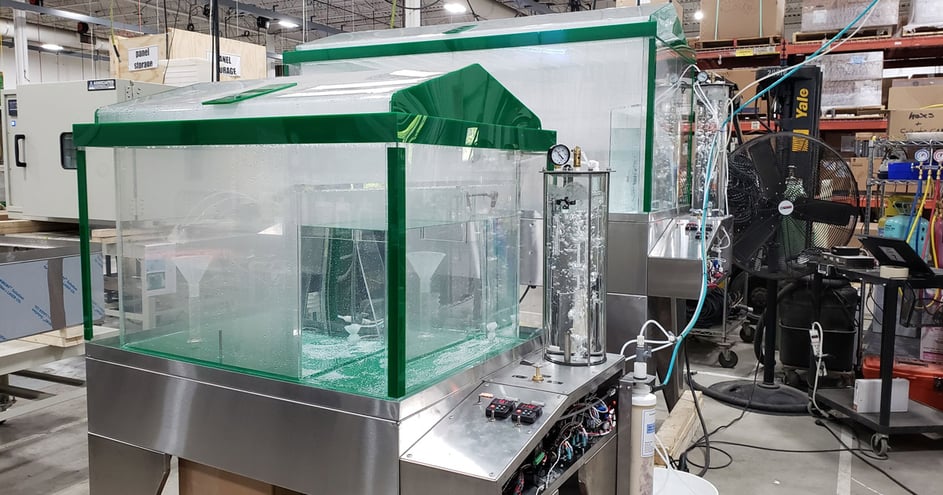
Unpacking Your Salt Spray Chamber
Exercise caution when opening the packaging. AES MX Series salt spray chambers are constructed from clear Lucite sheeting, a durable material, but one that can crack during shipping. Carefully inspect the chamber for any damage before proceeding. Even small cracks will spread over time, so contact AES immediately if you find any signs of damage.
Once unpacked, place the chamber on a hard, level surface in an area with plenty of ventilation. Salt spray chambers are designed to create a corrosive atmosphere, so adequate surrounding space and airflow are important to minimize rusting in the test area.
Power and Utility Requirements
The electric panels and chamber come completely pre-wired and ready for use. The power source must be properly grounded — standard power requirements are listed in your chamber's user manual.
For water, salt spray chambers require single distilled (demineralized) water. Untreated tap water should always be fed through a demineralizer cartridge before use. To determine the capacity of your demineralizer cartridge, use this formula:
1,600 grains TDS ÷ 17.12 ppm = capacity in gallons
Replace the cartridge when three-quarters of the pellets have changed to their "used" color. Demineralizer systems can be purchased directly from the AES sales team and parts department.
Salt Spray Nozzle Assembly
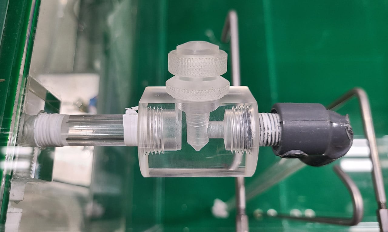
All AES salt spray chambers ship with an atomizing nozzle already installed. If you ever need to replace it, follow these steps:
- Apply a quarter-inch wide strip of Teflon tape to all joints. Avoid letting any tape enter the inside of the pipe — apply it two to three threads back from the end of the pipe.
- While keeping all foreign materials out of the pipe, screw the short acrylic quarter-inch pipe nipple into the tapped hole on the inside of the chamber. Hand tightening is sufficient.
- Screw the salt spray nozzle onto the acrylic nipple from Step 2 and tighten by hand. Orient the nozzle so the spray direction faces the front of the chamber and the other tapped hole points downward.
- Screw the long acrylic quarter-inch threaded pipe (called the siphon tube) into the tapped hole at the bottom of the nozzle until snug.
- Place the nylon mesh strainer over the other end of the siphon tube and secure it with rubber bands. If a special MIL-STD-202 or MIL-STD-810 filter is used, attach it to the end of the siphon tube instead.
- Place the salt reservoir cover on top of the salt reservoir.
Salt Spray Chamber Ventilation
To prevent back pressure within the chamber, it must be properly exhausted. Install a non-corrosive ¾-inch pipe from the chamber exhaust to a point outside the building. Follow these guidelines:
- Keep the pipe as short and straight as possible
- The pipe should slope continuously downward from the chamber — no liquid traps
- Shield the outdoor end from wind and air currents
- Avoid flexible hose unless you can ensure it won't sag and create liquid traps
- For exhaust runs longer than 10 feet, use a 2-inch line
- If the exhaust must run upward (e.g., through the roof), use a T-fitting rather than an elbow, and add an 18-inch drop line and drain to keep the line clear at all times
Salt Chamber Air Supply
MX Series chambers require clean, oil-free compressed air. The chamber comes pre-fitted with a valve marked "air" at the rear. Typical compressed air requirements for the MX Series are:
- Flow: 1.5 SCFM (0.71 L/sec) to 4.0 SCFM (1.89 L/sec)
Pressure: 6–10 PSIG (depending on model)
How the Chamber Works
Before running your first test, it helps to understand what's happening inside the chamber.
MX Series chambers use double-wall construction that circulates warm air between the inner and outer walls via blowers and heaters located in the base. A thermostat within the testing area maintains the internal temperature at 95°F (35°C) ± 2°F.
The salt atmosphere is generated by the atomizing nozzle, which uses compressed air to siphon salt solution from the reservoir. Before reaching the nozzle, the compressed air is warmed and saturated by bubbling it through heated water in the saturation tower, which is kept at 114°F (45.5°C). This higher saturation temperature causes a small amount of condensing moisture to continuously purge the nozzle, preventing salt crystallization and clogging — ensuring a uniform atmosphere inside the chamber at all times.
The salt solution should be prepared to match your test specifications. Many standards (such as ASTM B117) require a 5% sodium chloride solution — approximately 2 lbs 1 oz of sodium chloride per gallon of distilled or demineralized water.
Operating Your Salt Spray Chamber
Start-Up Procedure
Follow this sequence at the beginning of every test:
- Confirm the chamber is positioned on a level surface.
- Connect the vent line and ensure it is free of restrictions.
- Fill the saturation tower reservoir.
- Fill the salt reservoir to within one inch of the top and replace the cover. (Note: the solution temperature should be at or below 95°F when filling.)
- Fill the top cover trough with distilled or demineralized water and close it. This water seal prevents salt fog from escaping into the room — refill it periodically and ensure the chamber is level for a proper seal.
- Connect the compressed air supply and verify it is at the correct pressure.
- Open the chamber air valve.
- Turn the compressed air supply on.
- With the selector valve in the salt spray position, turn the tower switch to On.
- Turn the circulation and chamber switches to On, then verify:
- Air is bubbling up through the saturation tower
- A fine mist is emerging from the atomizing nozzle
- Air is flowing through the exhaust line
- No air is bubbling through the water seal around the cover
- After approximately 30 minutes (once the chamber pilot light begins cycling on and off), check that the chamber and tower temperatures have stabilized within spec.
- Verify thermostat operation by observing the electric panel pilot lights — they should cycle when temperatures near their setpoint values.
- Confirm the salt spray nozzle is operating properly.
- The chamber is now ready for use.
Shutting Down
At the end of the test, place the selector switch in the purge position. Confirm that air is being admitted directly into the chamber and that it flows freely from the exhaust before powering down.
Need Help?
If you have any questions about installation, setup, or operation, contact an AES representative. AES offers on-site repairs, maintenance, calibrations and is always available to walk you through any step of the process.


